07-23-06 Electrical
After a few days of work the electrical system has been installed on all four modules.
I am using a Digital Command Control system by Digitrax on my layout. This will allow me to have multiple trains running at the same time. One train could be working in the yard while another one runs around the main line. Each locomotive has a uniquely addressed decoder. A throttle will only control the locomotives whose addresses were entered into it. You can have multiple throttles controlling trains on the same stretch of track.
I decided to separate the layout into four circuits. I am going to use a circuit board available form Digitrax that will take the output of the Digitrax controller and separate it into four outputs. Each output can be set up as a circuit breaker or an auto reversing circuit. I am going to use three as circuit breakers, and the one as an auto reversing circuit. I have wired the yard as one circuit and the main line as two circuits.
I used the auto reversing circuit for a piece of track that connects the front track to the rear track. As a locomotive enters the reversing track, the track�s polarity will switch if needed to match the polarity of the track the locomotive is coming of. As the locomotive leaves the reversing track, the track�s polarity will switch to match the polarity of the track the locomotive is entering. The locomotive will continue traveling in the same direction no matter what the polarity is when using DCC.
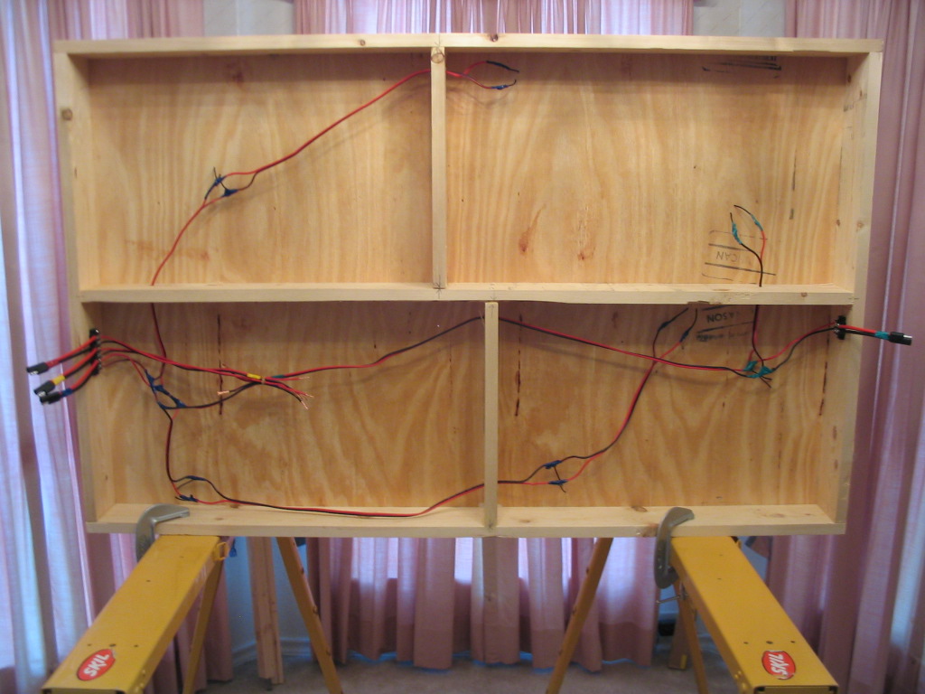
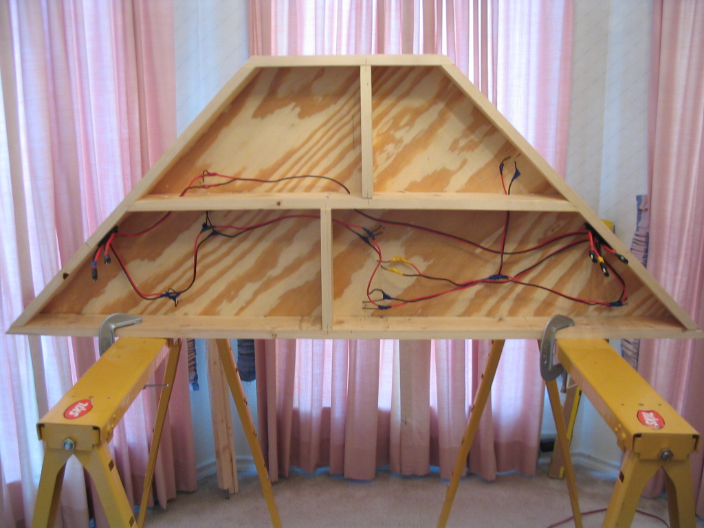
The wiring was not too hard, but it took a while. First, I soldered three inch 18 awg. wire feeders to the track. The trick to this was soldering quick enough to avoid melting the plastic ties. I soldered the feeders to 14 awg. bus wire. I connected the bus wire to terminal strips on either side of the module. I attached connectors to the terminal strips. I used a meter to check for short circuits in each circuit on each module as I was wiring them. I distinguished the different circuits using colored electrical tape.
On the existing yard module, all I had to do was add a terminal strip and connector. The original NTRAK was a little more involved. I connected the bus lines going to the middle and rear tracks. I had to swap the polarity going to the rear track. I connected the bus line for the front track to an existing auxiliary line so I would not have to rewire it with a different gauge wire. This module already had terminal strips, so I just had to attach connectors.
The next steps are to attach the legs, set up the layout, cut joining tracks, and run trains.